 |
|
|
|
“…..uncalibrated elbows will be subject to a tolerance (uncertainty) of about + 4%. With a calibrated elbow, the tolerance should be comparable to that for other types of differential pressure meters. With either calibrated or uncalibrated elbows a high degree of repeatability is attainable." (Fluid Meters - their theory and application ASME 6th Edition 1971) Measurells can be constructed with identical specifications as the line in which it will be installed. Non-standard construction to date includes titanium, 90/10 cupro nickel, fiberglass and cast iron. We have also provided special features such as coal tar and epoxy coatings, galvanizing and nickel plating. Note: calibration is performed after any internal modifications. The Measurell is completely non-invasive and thus permanent pressure losses are minimal and can be easily calculated from readily available tables of permanent pressure loss through elbows. Generally, permanent pressure loss is about 1/3 of pressure loss using an orifice plate with comparable beta ratio and the Measurell signal is up to 4 times greater.( See Fig. 5 ) Much higher differential signals are produced (up to 4X) than those of venturi tubes or orifice plates with comparable beta ratio. This is caused by the effect of the centrifugal force of the fluid as it passes through the elbow. This is especially significant with reduced throat configurations. A simple, effective modification to previously conventional tap placement, a unique discharge section design, and individual shop calibration have made the Measurell, i.e. elbow flow element, a non-invasive primary device available as a replacement for the familiar orifice plates and venturiis. All types of line material, weld specifications and end connects are customer specified. Standard accuracy of + 1.5%, excellent repeatability and very low permanent pressure drop are gaining the Measurells a widespread use in the monitoring of gases, liquids and slurries including corrosive medias and other problem fluids.
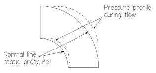
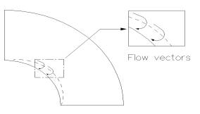
FIG. 1: PRESSURE PROFILE By placing pressure ports or taps in the elbow and sensing the difference in pressure between the inner and outer radii, the flow rate can be determined. Past efforts to use elbow flow meters have usually tried using taps inserted at the 45º position along the bend. However, problems arise since pressure distribution is sensitive to details of tap finishing, upstream surface roughness, internal weldment and manufacturing variances. Research using flow visualization techniques, has shown that stagnant or separated regions of flow can occur, primarily on the inside bend (Fig.2).
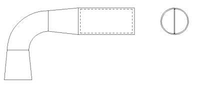
FIG. 2: FLOW SEPARATION The size of this area is influenced by all the previously mentioned factors. A pressure tap placed within such an area, results in variable readings and generally unsatisfactory flow-metering performance. Our investigation and development resulted in special tap placements to ensure reliable and repeatable differential pressure signals and thus flow-metering. Measurels are individually calibrated and if necessary, include three diameter lengths of approach piping incorporating anti-swirl vanes. Although standard accuracy is + 1.5%, calibration accuracy of + 0.3% can be achieved for special circumstance with ASME published repeatability of + 1.2%. Applications for low flow rates, or low-density fluids such as natural gas or steam normally require elbow assemblies (Fig.3) incorporating a size reduction at the elbow, followed by a gently expanded section for excellent pressure recovery.
FIG. 3 REDUCED CONFIGURATION Signal & Pressure Loss
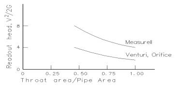
FIG. 4: SIGNAL GENERATION From theoretical considerations, an elbow with no restriction develops a pressure difference of almost two velocity heads while an orifice or venturi of course develops no signal at all with no restriction. As the throat (elbow diameter) is reduced below line size, the combined effects of constriction and centrifugal force produce a much larger read-out signal than for either venturi meters or orifice plates at the same restriction ratio. This effect is of great advantage for low flow measurement, as well as for gas, steam, or airflow determinations. Gradual expansion back to full line size to minimize friction loss results in extremely low permanent pressure loss. A comparison of pressure loss for Measurels, orifices and venturi tubes at different restriction ratios is indicated in (Fig. 5).
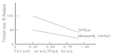
FIG. 5: PERMANENT PRESSURE LOSS Although Measurells in the reduced configuration have a permanent pressure drop it is only a fraction of the pressure loss of an orifice plate measuring the same flow. Venturi tubes also have low frictional loss but are more susceptible than Measurells to flow irregularities and as a result must be protected to a greater degree against inlet swirl by straightening vanes, grids or long lengths of entry pipe. Orifice plates suffer similar disadvantages as the venturi but as mentioned previously, also have a much higher friction loss. The Measurell features of high signal generation and very low permanent pressure loss are particularly important in natural gas pipelines or steam flow applications, where orifice plate losses result in large energy consumption. Effect of Approach Piping
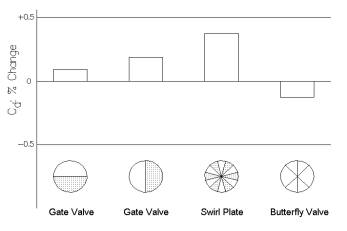
FIG. 6: EFFECT OF UPSTREAM DISTRUBANCE ON DISCHARGE COEFFIEIENT A gate valve type obstruction (half shut, valve stem in the plane of the elbow) had less than 0.1% effect on discharge coefficient when located only 1.5 diameters upstream. The largest disturbance effect was due to a special in line plate, which produced a swirl velocity approximately equal to the Discharge Coefficient
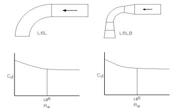
FIG 7: ELBOW REDUCTION EFFECT ON DISCHARGE COEFFICIENT
Special Taps for Contaminated/Corrosive Liquids, Gases, Slurries This has great practical advantages for use in contaminated fluids, or corrosive gases and liquids in addition to slurries and sewage that are prone to plugging smaller pressure ports present in venturiis or orifice systems. Simple periodic blowout or purging systems can also be devised with excellent results. The Measurell is available with isolating diaphragm mechanisms inserted flush with the inside surface of the elbow, completely isolating corrosive working fluids from a conventional instrument air read-out system. AREAS OF APPLICATION To date, thousands of Measurells have been installed in a variety of applications over a wide range of service conditions and line specifications. The advantages of using a Measurell vary with the installation. Measurells with isolating diaphragms have found ready use for sewage and slurry measurement. Furthermore, the very low-pressure drop and excellent repeatability enable economical service for gas pipeline compressor surge control. Cast Measurells are extensively utilized in HVAC systems as an economical and easily installed means of system balancing. In many cases the fact that the Measurell substitutes for an existing elbow means low costs, while the relatively short approach lengths have resulted in close coupling with pumps or valves and elimination of long lengths of approach piping. To date construction materials have included Cupro-Nickel, stainless steel (cast and forged) cast iron as well as the catalogue standards of PVC, cast bronze and forged steel. The latter has included Sch. 40 to Sch. 120 with any type of pipe connection and weld specifications. The variety of service conditions and line specification applied to Measurels are continually expanding. ALTHOUGH THE EXAMPLES BELOW USE MEASURELLS, THE SAME FORMULAS ARE USED TO SELECT FLO-PROBES FOR ELBOW OR STRAIGHT LINE INSERTION - WHEN THE APPROPRIATE "C" IS UTILIZED . h = S(Q/C)², where ; S = specific gravity of the fluid at line conditions Air: The selection procedure is as indicated above, except a constant factor to account for conversion of units and air density must be made using the following formula. h = (0.896)(d)(Q/C)², where ; Q = CFM at line conditions, Steam: The selection procedure is as above using the following formula h = (v)(W/C)²/4015, where; Natural Gas: The selection procedure is as above using the following formula h = 32.6(MZ)(T/p)(MMSCFD/C)², where; MMSCFD = gas flow rate, million standard cu. ft/day |